Tuesday, April 14, 2015

WiFi and Integrated Power

I'm working on my next version.  It will have more compact power supply, create a true +/-12v square wave and utilize an ESP8266 to set timers and current.

This will make it very compact and should fit in a much smaller enclosure than my last attempt.  Most of the space in the enclosure to the right is take up by power supply and wiring.

Sunday, January 25, 2015

Thoughts on what's next

I have to areas of improvements that I'm working on.

WiFi
I'd like to integrate a inexpensive wifi controller and have it run the entire show.  I'm currently learning a lot about ESP8266.  I would replace the ATTiny85 controller and program the ESP8266 WiFi processor to directly drive the controller (click link for how).

One side effect of using the ESP8266 is that it doesn't have an ADC (that I can find), so I can't poll the voltage of the sense line to drive the vehicle state algorithm.  That means I'll probably use an additional OpAmp/comparitor in an inverting "1-bit ADC".  The ESP8266 will be skinny dumb and happy and just have code that checks...


Sense LineStateDescription
All LOWAOff/Fault
Low/HIGHBPowers On, may be plugged in
All HIGHCVehicle requested charge
Still need denouncing (for noise); but the basic algorithm is something like...  
If we're in "B" and are changing state to "C", enable charging.
If we're charging and we ever see "A" or "B" stop charging


Solid State
I'd like to go solid state.  Dual opto-isiloted connected to a 40A triac. It's even cheaper and smaller and I can easily integrate it on the board.  Example Circuit

Onboard power supply
So you feed the board 240VAC and a pico-sized (150ma) onboard power supply will convert it down to 3.2v for the controller.


Current sense
Use an inexpensive current sense.  I can send back the current usage in status so it can be sent to the control website.


The Quadracorn
I'm building a four channel controller with all of the above.  That may become my regular circuit that I'll use for everything.  There's very little additional cost in making the circuitry I won't populate.


Friday, November 28, 2014

Reflections and TinyEVSE v2.0 Semi-final

"Art is never finished, only abandoned"


A few things I've learned along the way

I have been working on a very simple, low-cost functional, compact EV charger;  here's my ramblings on what I've got so far.
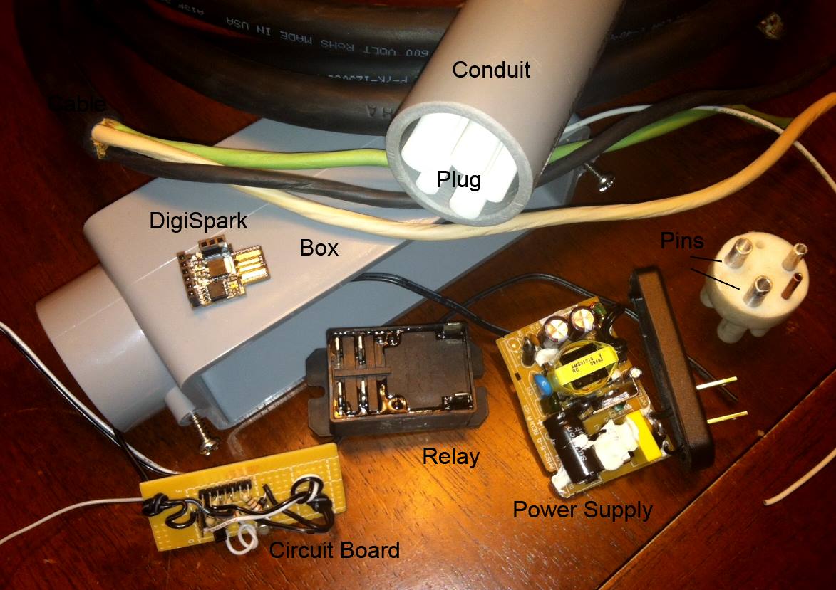

The Plug

I can't make my own plug easily.  I'm certain I can get one built, and it would work, but the risk and quality controls required to make the complex receptacle are too beyond my scope.


The Circuit Analysis

My first version of the square wave level-shifter (5v -> 12v) just used a very simple inverted NPN configuration.  It is very simple, but wastes a fair amount of current when the circuit is dropped.  Also, when gate closes the circuit the output voltage was about 27mv.  There's always going to be some leak voltage in this configuration.
! NOTE - ONLY SEMI - WORKS !
So, I own a Nissan Leaf and a Chevy Volt.  I plugged everything up and the Volt worked great, the Leaf... Never got beyond the "plugged-in" beep.  So it never recognized my +26mv to +12v square wave as the pilot function.  Oddly a very early test used a simple Op-Amp for this level-shift and the Leaf did recognize that form.

Cuiriouser and curiouser... After analyzing in CircuitLabs, I found the op-amp version did not leak and actually went -2mv.  I do not have the equipement to test this experimentally, so I am unsure if this is a simulation effect or an actual LRC overshoot.  Either way, the Leaf did accept this signal as accurate

Additonal research: I think a "high side switch" (HSS) NPN/PNP configuration could also work better.  It was more efficient as it wasn't trying to sink 12v to gound through a 1k.  It got as low as 2mv, much closer, but not drop through zero as the op-amp did.  I knew the op-amp worked before, simulated better, so my v2 uses the op-amp.

This version works!
Link to CircuitLab TinyEVSE circuit

Micro Controller

I chose the ATTiny85 for all these reasons:

- Very inexpensive (~$.80 in quantity)
- It has all the power of much larger MC
- Shares much of the same traits of the wildly popular Arduino processors ATMega328
- Small 8-pin package
- Very low power
- Very simple to configure, with an internal clock that's accurate enough

Because TinyEVSE has very low processing requirements, I lowered the internal clock to 1mhz, to save power.


Code

It's really not complicated...  Here's an overview;  you can find it here

It all starts with a 1000hz (1ms) square wave, the ATTiny85's built in hardware PWM is the best choice for generating this wave.  Some research and you can download some apps to tell you how to configure that.  To use OCR1B on PB4 1khz frequency, you need to set;

      // 1khz Timer1 (PB4)
      OCR1B = 250; 
      TCCR1 = 0x83;

The duty cycle of the wave sets EVSE's request current.  analogWrite() achieves this.

// set EVSE current capacity in Amperes
// see: https://code.google.com/p/open-evse/wiki/J1772Basics
// 
void SetCurrent(int amps)
{
analogWrite(PILOT_PIN_OUT, 256 * BoundAmps(amps) / 60);

If you do the math, duty cycle is requested amps / 0.6 in %.  So if I am requestig 15A; 25% duty.

This square wave signal is run through a level-shift to 12v to the car.  The car then chops the +12v to +9v.  That tells me, we've plugged in.  Then the car further chops the signal to +6v.  That's my signal to get in gear and energize the relay.

I do the sense line / EVSE state analysis using a short 100 iteration min/max polling loop on the sense in  GetPilotMax().  That output is fed into GetState(int pilot) which "de-bounce" filter the output the true current EVSE state.  This removes the chance that random signals cause eronious state changes.

At the highest level this code snip sums it up nicely:

if (HasStateChanged(GetState(GetPilotMax())))
{
  SetCurrent(currentRate);
  if (EVSE_PILOT_STATE_C == evsePilotState)
    StartCharging();
  else
    StopCharging();
}

Program the board
I built a programmer to flash my controller directly.  I used a UsbTinyISP, you can get them on eBay cheaply.  You can program this using the Arduino IDE, but I have fallen in love with CodeBender.cc


Board

I have spent WAY WAY WAY too much time tinkering on EagleSoft CAD.  I have made at least a dozen versions of this.  Some use 12v DC Relays, some used 240vac 2P contactors.  Ultimately I went with the cheaper compact 12v relays because I can run them on 120/240VAC.  They are marginally simpler and marginally cheaper.  But I do think a 2P 240vac contactor could work really well using an optical SCR to energize the coil and it would last much longer.  But it is much larger than the PB 12v relays.

A few criteria for the board design;

- Simple
- Compact
- Convenient to assemble; connects directly to the relay pins
- Single sided so I could etch it myself
- Huge over sized traces anyone (even me) could etch without issue
Final Artwork

Eagle Files:

Schematic
Board

So build it already!

To make a "TinyEVSE" the best thing to do;

- Buy a plug on eBay, they sell for about $100.

- Build a TinyEVSE controller board for a ATTiny85; $20


- Buy a relay $7

- Buy/Convert a small 12v power supply (200ma+)

- Buy or build a box

So total cost to build your own 30A Level 2 EVSE; well under $150.


Formal BOM :

DIP
PartValueDevicePackageDescriptionPROD_IDVALUE
U1TINY85-20-DIPATTINY45TINY85-20-DIPDIP08Atmel 8-pin 2/4/8kB flash uCIC-09445TINY85-20-
IC1LM340MP-05LM340MP-05SOT223Positive VOLTAGE REGULATOR
IC2LM321MFLM321MFSOT23-5Low Power Single Op Amp
Q1MMBT5088TRANSISTOR_NPNSOT23-ISOT23Generic NPN BJT
D1DIODESMBSMB-DIODEDiodeDIO-09646
C21.0uF1.0UF-25V-+80/-20(0805)0805CAP-11625CAP-116251.0uF
R120k0.75OHM1/4W1%(0805)0805RES-08474RES-084740.75
R21k0.75OHM1/4W1%(0805)0805RES-08474RES-084740.75
R310k0.75OHM1/4W1%(0805)0805RES-08474RES-084740.75
R4200kR-US_MELF0204RMINI_MELF-0204RRESISTOR, American symbol
R5120k0.75OHM1/4W1%(0805)0805RES-08474RES-084740.75
R61k0.75OHM1/4W1%(0805)0805RES-08474RES-084740.75

Monday, July 14, 2014

!IT WORKS!


I finally figured out what I was screwing up, I didn't wire the proximity resistor, on pin 5.  The fancy J1772 cord I purchased already wired into the nozzle.


I hooked it up, the Leaf honked (connected), I turned on the power hit the Leaf Timer override and it charged and without smoke.  I left it in for about 2 minutes, shut it down, disconnected and felt for heat, there was none.

This version is on a PCB I made and it has a built in nrf24l01+ 2.4ghz transceiver, so I can add remote control.  I'm going to use it to feed a website on a RaspberryPi and set charge timers and requested amps rate.


Monday, September 2, 2013

The vision of Ubi Vis

The purpose of this little project of mine is to get charging stations everywhere!

We need charging stations on every lamp post in every parking lot in every retailed, public building and sky scrapper parking garage.  They just need to be everywhere all the time.  The only hindrance is our will to make it happen.

What about a program to offer free charging stations to anyone who wanted them, as many as they want!  Why not a 2D barcode on the box and do it honor system?  I know it sounds naive, I don't care.

The Design

I finalized the software and hardware to control the relay.  This is the heart of the charger and it means I am very close to an operational unit, I just need to plug it all together.  When I created the sense amplifier, I used an PNP (2N3906) transistor instead of an NPN (2N3904), they where mixed in the same small bag and very faintly written. That got me very confused for a long while.  Once I replaced them... wham it all worked first try.  Very happy!


It works perfect fine on 120 or 240vac.  If it senses 120vac, it requests that the car not pull any more than 10A.  On 240vac, it asks for 30A.

/*
  J1772/EVSE Lite
  (c) 2013 Bruce Meacham

  Used to control the charging of an Electric Vehicle from a DigiSpark ATtiny85/Arduino controller
 */

#define acInputPin       0  //P0 -- INPUT: AC->DC input.  Used to figure out if we're charging on 120vac or 240vac
#define currentSelectPin 1  //P1 -- INPUT: Switch, off(open) is "low current", on(closed) is "high current"
#define pilotSensePin    1  //P2 -- INPUT: Analog sense input, used to determine if the car is connected and wants to be charged
#define pilotPWMPin      4  //P4 -- OUTPUT: 1khz PWM duty cycle tells car requested current (see J1772 spec)
#define relayPin         5  //P5 -- OUTPUT: Connects to a transistor that will turns on the relay to energize the L1/L2

// ___INVERTER__
#define lowCurrentDuty  42  // 10 Amps (16.6%) -> 256 * 10A / 60 (it's inverted)
#define highCurrentDuty 128 // 30 Amps (50%) -> 256 * 30A / 60

// Counters used to determine if the car wants to charge state
int countGoHot = 0;
int totalCount = 0;

// Minimum cut-off, used to determine if we're even minimialy functional
#define pilotLowCutOff 10
//  0v - error/broken
//  12v (4.5v after splitter) not plugged in
//  9v  (3.6v after splitter) plugged into vehicle
//  6v  (2.4v after splitter) vehicle ready to charge
//  3v  (1.2v after splitter) vehicle ready to charge, vent required
//  7.5v is the mid-point x-over to "ready to chage" (3.2v after splitter) =>  652
#define pilotHighCutOff 652

#define cyclesToCheck 200
#define hotThreshold ((cyclesToCheck) / 10)  // 10% of the highs need to be in this range
#define minAC      40    // defines the minumum value for the 120vac range
#define maxAC120   500   // defines the maximum value for the 120vac range

void setup()  {
  // Initialize the PWM signal for pilot
  analogWrite(pilotPWMPin, lowCurrentDuty);        

  // Setup the digital I/O ports -- not analog
  pinMode(relayPin, OUTPUT);  
  digitalWrite(relayPin, 0);   // set it high (it's inverted)
  pinMode(currentSelectPin, INPUT);
}

void loop()  {
  // Sense the pilot and figure out if which range we're in
  //  0v - error/broken
  //  12v (4.5v after splitter) not plugged in
  //  9v  (3.6v after splitter) plugged into vehicle
  //  6v  (2.4v after splitter) vehicle ready to charge
  //  3v  (1.2v after splitter) vehicle ready to charge, vent required
  int pilotSense = analogRead(pilotSensePin); 
  if (pilotSense > pilotLowCutOff && pilotSense < pilotHighCutOff)
    countGoHot++;

  totalCount++;

  if (cyclesToCheck == totalCount)
  {
    // set the relay hot if we had some lows (bottom of the phase) and very few highs (not plugged or not ready)
    // the relay circuit is inverted
    if (countGoHot > hotThreshold)
      digitalWrite(relayPin, 1);
    else
      digitalWrite(relayPin, 0);
    totalCount = 0;
    countGoHot = 0;
   
    // Read the current select switch and set the duty cycle accordingly (0-Low Current, 1-High Current)
    byte currentSelect = digitalRead(currentSelectPin);
    int acIn = analogRead(acInputPin);
    byte duty = (0 == currentSelect /*|| (acIn > minAC && acIn < maxAC120)*/) ? lowCurrentDuty : highCurrentDuty;

    analogWrite(pilotPWMPin, duty);        
  }
}


Thursday, August 15, 2013

Ubi Vis Where you Want, Latin


If you want electric chargers on every lamp post, a good place to start is making them cheaper than the lamp post! 

How do you make an inexpensive charger... think simpler.  I started the project trying to determine how I could do this with the simplest and least expensive component around.  The system must charge a Leaf at up to 30 miles every hour on common electrical supply ubiquitous in any structures electrical system.  The cheapest commercial system costs $750.  The only OpenSource/DIY project costs $300.

I built the prototype J1772 compatible Level-2 (120 or 240v up to 30A) for $77.54 total!  This same methodology could yield a commercially viable system for $40-50. 

Great, simpler; sure how?
  • Uses the simplest controller, DigiSpark
  • Does only charging; doesn't check for wildly unusual conditions (stuck relay, GFI, power.
  • small electronic parts list; two transistors, 5 resistors and a diode
  • Built the J1772 Socket, commercial units come at "non-standard" cost ($130+)
  • Use commercially available electric parts (conduit, boxes, cord, etc)
Parts:
  • DigiSpark
  • J1772 Plug
  • Relay
  • Any 12vdc power supply (you have one lying around)
  • 2-NPN Transistor
  • Resistors (come in 5-packs)
    • 5-1k
    • 5-15k
    • 5-10k
  • ft 10/3 outdoor ruberized wiring
  • 1-1/4" PVC conduit (45-bend)